|
|
|
| The following is a listing of various hardware components,
which can be purchased and used with your Serial port. |
| Mouse - One of the most commonly used devices for serial
ports, usually used with computers with no PS/2 Ports or laptop
computers. |
| Modem - Another commonly used device
for serial ports. Used commonly with older computers however is also
commonly used with computers for its ease of use. |
| Network - One of the original uses of
the serial port, which allowed two computers to connect together and
allow large files to be transferred between the two. |
| Printer - Today is not commonly used
device for serial ports (not applicable to the DB25 or Parallel Port).
However was frequently used with older printers and plotters. |
|
|
|
|
|
|
| The serial port on
your PC is a full-duplex device meaning that it can send and receive
data at the same time. In order to be able to do this, it uses separate
lines for transmitting and receiving data. Some types of serial devices
support only one-way communications and therefore use only two wires in
the cable - the transmit line and the signal ground. |
|
|
|
|
|
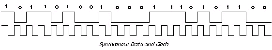
| Synchronous Data and
Clock |
| When Modem Is use
to send data, the clock it combined with the data to modulate an analog
signal. The clock is derived the analog signal that is receive and used
to decode the synchronous data stream. If the Modem is in synchronous
mode, the clock is often output to the modem serial port. See figure
below.
If the modem is in
synchronous mode, the clock that is derive from receive
analog signal is used to decode the data, but is not output on the
modem serial port.
|
|
 |
|
|
| Synchronous Transmission |
| In synchronous
transmission, grouping characters together, and doing away with the
start achieve greater efficiency and stop bits for each character. We
still envelop the information in a similar way as before, but this time
we send more characters between the start and end sequences. In
addition, the start and stop bits are replaced with a new format that
permits greater flexibility. An extra ending sequence is added to
perform error checking.
There are variations of
synchronous transmission, which are split into two
groups, namely character orientated and bit orientated. In character
orientated, information is encoded as characters. In bit orientated,
information is encoded using bits or combinations of bits, and is thus
more complex than the character orientated version. Binary synchronous
is an example of character orientated, and High Level Data Link Control
(HDLC) is an example of bit orientated.
In asynchronous
transmission, if there was no data to transmit, nothing was sent. We
relied on the start bit to start the motor and thus begin the
preparation to decode the incoming character. However, in synchronous
transmission, because the start bit has been dropped, the receiver must
be kept in a state of readiness. This is achieved by sending a special
code by the transmitter whenever it has no data to send.
|
|
|
|
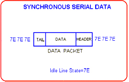
In
bit-orientated protocols, the line idle state is changed to 7E, which
synchronizes the receiver to the sender. The start and stop bits are
removed, and each character is combined with others into a data packet.
User data is prefixed
with a header field, and suffixed with a trailer field,
which includes a checksum value (used by the receiver to
check for errors in sending).
|
|
| The header field
is used to convey address information (sender and receiver), packet
type and control data. The data field contains the users data (if it
can't fit in a single packet, then use multiple packets and number
them). Generally, it has a fixed size. The tail field contains checksum
information, which the receiver uses to check whether the
packet was corrupted during transmission. |
|
|
|
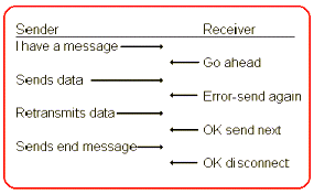
| Character Orientated Protocols (COP) |
| In
character-orientated protocols, each character has significance, In
other words, when a character arrives at the receiver, the character
has
two meanings, it's either a data byte, or it's a control byte (which is
used as information signals between the sender and receiver). The main
COP in use today is known as BI-SYNC, or binary synchronous.
Communication takes the form of a
handshake between the sender and receiver. Communication of a message
from sender to receiver takes the following format,
|
|
|
|
As you can see, this is a HALF-DUPLEX (which
means only one side talks at once) method of
communication. Long messages are broken up into a series of
smaller data packets, and transmitted one at a time across the link.
Each packet is acknowledged before the next packet is transmitted. |
|
| If a
packet is not acknowledged, the sender will time out and then
retransmit
the packet. If the receiver acknowledges the packet, the sender sends
the next packet and so on until the entire message has been sent. If a
packet is received and contains errors, the receiver will send a
negative acknowledge, which requests the sender to send it again.
Data bytes contain data according to the
ASCII code (for text), or simply a value between 0-255 for binary data.
Control bytes determine the behavior of the communication link, and are
used for a range of different purposes.
|
|
|
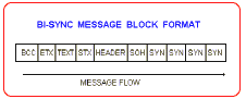
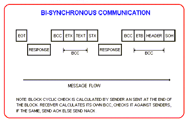
| Binary Synchronous Message
Blocks |
| Messages are sent
in blocks. Message blocks have the following format, |
|
|
|
Each message block can
contain up to theree parts,
- An optonal header
- The text
- A trailer
The control characters used to identify these parts are,
- SOH indicates the header follows
- STX indicates the text follows
- ETX ubducates the end of the text block
|
| SYN characters are
used to establish synchronization between the sender and receiver. The
message block follows the SYN characters.
The sender splits a long message up into
a number of small message blocks. The trailer for each block consists
of
a block check character (BCC). As the message block is transmitted,
both
the sender and receiver each generate their own BCC. At the end of
receiving the trailer, the receiver compares its own BCC against that
of the senders. If they are the same, this indicates the block has been
successfully received without errors, so the receiver will reply using
a
positive acknowledge (ACK). If the BCC of the receiver does not match
that of the sender, the receiver knows an error has occurred during
transmission, and will instruct the sender to re-send the block by
replying with a negative acknowledge (NACK).
|
|
|
|
| A preset number
of repeated attempts to re-transmit a corrupted message block (upon
receiving a NACK) will be made before the sender will abort the
transmission. |
BACK
TO TOP |
|
|
|
| The type of serial
data communications supported by a PC's COM port and usually the type
used by PCs when using modems.
Literally, "not
synchronous."
When used in low-speed
data communications, it means that there is no predefined timing
between the characters sent; typically, the characters are sent as
they are typed by some human (and you know how unpredictable humans
are). The method was designed to handle the expected case that the
sender's and receiver's bit rates will never be exactly the same and
only one character will be ready to be sent at a time.
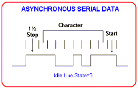
The following
descriptions, and figure below, are for the polarities used on EIA-232
circuits. While there are no data to send (idle), the data circuit is
at a negative voltage.
When a character of data
is to be sent, the UART first sends a start bit (a one
bit-time duration positive voltage), which is of the
opposite polarity of what was happening.
The transition from
negative to positive voltage occurs exactly at the boundary between
two bit-times, so the receiver now knows where the bit boundaries are
(that is, bit synchronization and character synchronization have
been achieved).
The receiver senses this
transition, waits 1/2-bit-time (the receiver must be
reconfigured to nominally the sender's bit rate) to the center of the
start bit, and samples (reads) the input again. If it is
still a positive voltage, then the receiver can be somewhat sure that
the initial edge was not just noise.
The receiver then begins
assembling the first character of data (in this case, an
ASCII d, by waiting a full bit-time, to the center of the first data
bit
(data are sent LSB first).
The input
is then sampled, and the first data bit (a binary 0 in this case) is
received. This is continued for (typically) 8 data bits total (the
receiver must be reconfigured to the same number of data 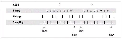
bits per character).
Then the receiver expects
a stop bit. It is a one bit at a time duration negative
voltage, which is generated by the sender's UART. If one is not
received
(the line is still positive), then the receiving UART indicates a
framing error (which may be interpreted as a break signal).
After the stop bit, either another
character (beginning with a start bit) or an idle (a negative voltage
of
any duration) begins. Figure 1 illustrates this process.
|
|
|
|
| Since the receiver
samples at the center of each bit-time, it can be as much as 1/2
bit-time off (too soon or too late) and still read the bit correctly.
Since both the sending and receiving clock may be wrong, each could be
up to 1/4 bit-time off (allowing for the worst case, in which one is
1/4
bit-time too fast and the other is 1/4 bit-time too slow). Since the
clocks get resynchronized at the start of each character (by the
transition to the start bit), the clocks have to be matched only so
that
they drift by less than 1/4 bit-time in the (approximately) 10 bits per
character. This requires an accuracy of 1/4 bit-time in 10 bits, which
is (1/4/10 =) 2.5%, which is easily accomplished.
Because of asynchronous
data communication's reliance on the addition of a
start and stop bit to every character of data, it is usually less
efficient than synchronous data communications (of every 10 bits sent,
2 are overhead). That is, 20% of the bandwidth is wasted on start and
stop bits, so a 9,600-bits/s line provides only 7,680 bits/s of
throughput. Some people call it start/stop data communications in
contrast to the synchronous data communications that are commonly used.
Asynchronous data
communications equipment needs to be configured for the following:
|
- Bit rate (such as
9,600 bits/s)
- Number of data bits
per character (such as 8)
- Parity type used
(such as none)
- Number of stop bits (usually one,
though stop bit durations of 1.5 and 2 bit-times are often settable,
but these were needed only for ancient mechanical teletypewriters that
needed more than one stop bit-time between characters)
|
|
| Both ends of a
link must have matching settings. |
|
|
| Asynchronous Transmission |
| Asynchronous
systems send data bytes between the sender and receiver by packaging
the
data in an envelope. This envelope helps transport the character across
the transmission link that separates the sender and receiver. The
transmitter creates the envelope, and the receiver uses the envelope to
extract the data. Each character (data byte) the sender transmits is
preceded with a start bit, and suffixed with a stop bit. These extra
bits serve to synchronize the receiver with the sender.
In asynchronous serial transmission,
each character is packaged in an envelope, and sent across a single
wire, bit by bit, to a receiver. Because no signal lines are used to
convey clock (timing) information, this method groups data together
into a sequence of bits (five - eight), then prefixes them with a start
bit and appends the data with a stop bit.
|
|
|
|
It's important to realize
that the receiver and sender are re-synchronized each time a character
arrives. What that means is that the motors/cams are restarted each
time
a start bit arrives at the receiver.
Nowadays, electronic
clocks that provide the timing sequences necessary to
decode the incoming signal have replaced the
electromechanical motors.
|
|
| This method of
transmission is suitable for slow speeds less than about 32000 bits per
second. In addition, notice that the signal that is sent does not
contain any information that can be used to validate if it was received
without modification. This means that this method does not contain
error
detection information, and is susceptible to errors.
In addition, for every
character that is sent, additional two bits is also sent.
Consider the sending of a text document, which contains 1000
characters.
Each character is eight bits, thus the total number of bits sent are
10000 (8 bits per character plus a start and stop bit for each
character). These 10000 bits is actually 1250 characters, meaning that
an additional 250 equivalent characters are sent due to the start and
stop bits. This represents a large overhead in sending data, clearly
making this method an inefficient means of sending large amounts of
data.
|
|
|
|
|
|
|
|