RS232 Connector
Pin Assignment
RS232 Cable Information
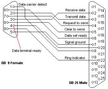
DB 9 and DB 25 Connection
RS232 Cable Information
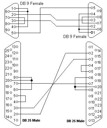
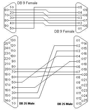
DB 9 and DB 25 Connection
The diagrams show the signals common to both connector types in black. The signals only present on the larger connector are shown in red.
Note: The protective ground is assigned to a pin at the large connector, in DB9 version protective ground connector to encloser.
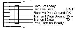
For the DEC modified modular jack. Although is differential (the receive and transmit have their own floating ground level) still possible to connect RS232 compatible devices with this interface.
RS232 DB 9 Pin
Assignment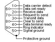 |
RS232 DB 25 Pin
Assignment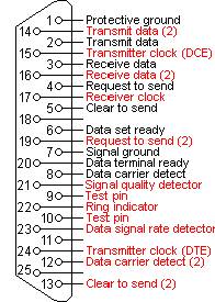 |
|
DEC MMJ Pin
Assignment
 |
DB9 to DB25 converter
The original pin layout
for RS232 was developed for a 25 pins D sub connector. From IBM-AT
machine popular 9 pins connectors are commonly used. RS232 DB9 to DB25
converter cable support mixed applications for 9 to 25 pins.
|
RS232 DB9 to
DB25 converter
 |
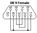
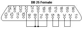
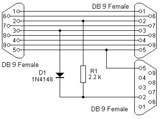
RS232 loop-back test plug
The following connectors can be used to self-test a serial port on your computer. The data and handshake lines have been linked. In this way all data will be sent back immediately. The PC controls its own handshaking.
Download test software from: www.pccompci.com
 |
 |
RS232
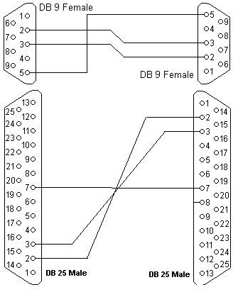
null modem cables
The using a null
modem cable is easiest way to connect two PC's.
For simple connections, a three line cable connecting the signal ground and receive and transmit lines is sufficient.
Depending of the software used, some sort of handshaking may however be necessary. Use the selection table to find the right cable for each purpose.
For Microsoft Windows use direct cable connection, the null modem cable with loop back handshaking.
Null modem cables with handshaking can be defined in numerous ways, with loop back handshaking to each PC, or complete handshaking between the two systems. The most common cable types are shown here.
Null modem with loop back handshaking
Null modem with partial handshaking

Null modem with full handshaking
Choose your null modem cable
| Use |
Simple
cable Without Handshaking |
Cable
with Loop back Handshaking |
Cable
with Partial Handshaking |
Cable
with Full Handshaking |
| Software
flow control only |
xxx |
x |
x |
x |
| DTE/DCE
compatible hardware flow control at low speeds |
- |
xxx |
xx |
- |
| DTE/DCE compatible hardware flow control at high speeds | - |
+ |
xxx |
- |
| High speed
communication using special software |
- |
- |
xx |
xxx |
| xxx |
Recommended cable |
| x |
Good
alternative |
| x |
Works, but not recommended |
| - |
Does not work |
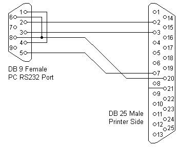
When a serial printer is connected to a PC, the handshaking is not symmetrical any more. In that case a cable is used where some handshaking lines at the PC side are looped back. On the printer side only the data lines and one handshaking line are used.
It is not difficult to
monitor the serial communication between two devices with a PC. To do
this you need the monitor cable, which is displayed in the next
picture. Two sockets are connected straight through. The PC is
connected to the third one.
This monitor cable taps communication from both sides. This means that if the two devices happen to talk simultaneously, the monitored information will be garbage. In most circumstances communication software works half duplex, in which case this problem does not exist.
This monitor cable taps communication from both sides. This means that if the two devices happen to talk simultaneously, the monitored information will be garbage. In most circumstances communication software works half duplex, in which case this problem does not exist.
| SPECIFICATIONS |
RS232 |
RS422 |
RS485 | |
| Mode of Operation |
SINGLE-ENDED |
DIFFERENTIAL |
DIFFERENTIAL | |
| Total Number of Drivers and Receivers
on One Line (One driver active at a time for RS485 networks) |
1
DRIVER 1 RECVR |
1
DRIVER 10 RECVR |
32
DRIVER 32 RECVR |
|
| Maximun Cable Length |
50
FT. |
4000
FT. |
4000FT. |
|
| Maximum Data Rate (40ft. -4000ft. for
RS422/RS485) |
20Kb/s |
10Mb/s
-100Kb/s |
10Mb/s
-100Kb/s |
|
| Maximun Driver Output Vlotage |
+/-25V |
-0.25V
to +6V |
-7V
to +12V |
|
| Driver
Output Signal Level (Loaded Min.) |
Loaded |
+/-5V
to +/-15V |
+/-2.0V |
+/-1.5V |
| Driver Output Signal Level (Unloaded Max.) | Unloaded |
+/-25V |
+/-6V |
+/-6V |
| Driver Load Impedance (Ohms) |
3k
to 7k |
100 |
54 |
|
| Max.
Driver Current in High Z State |
Power
On |
N/A |
N/A |
+/-100uA |
| Max.
Driver Current in High Z State |
Power
Off |
+/-6mA
@ +/-2V |
+/-100uA |
+/-100uA |
| Slew Rate (Max.) |
30V/uS | N/A | N/A | |
| Receiver Input Voltage Range |
+/-15V |
-10V
to +10V |
-7V
to +12V |
|
| Receiver Input Sensitivity |
+/-3V |
+/-200mV |
+/-200mV |
|
| Receiver Input Resistance (Ohms), (1
Standard Load for RS485) |
3K
to 7K |
4K
min. |
>=12K |
|
Standare EIA, Extended Distance Low Capacitance and EMI/RFI Double Shielded Data Cable.