|
CHAPTER
5 The Plug and Play features let hardware configuration for IRQ and I/O address is detected by BIOS automatically, so that it need not switch and jumper setting. The on board switch can be used to identify card number by the users (if you do not set the switch, the PnP BIOS will assign card number automatically). Select external clock or internal clock.. Identifies card
number Do not set up jumpers and
switch under power on condition, otherwise it may defective your
computer system.
The JP2 is used to select
external clock or internal clock; to select external clock, please
short pin 1 and 2, to select internal clock, please short pin 2 and 3.
When internal clock is selected, the communication speed is divided by
4.
a. Octal Speed for Internal Clock  The clock rate is 14.7456MHZ. The baud rate speed up to 230K. Under this configuration, the user setting baud rate maps to on board RS232 baud rate are list in the following. Please note that, you device driver may report original baud rate, however the speed of communication line is dual speed.
b. Octal Speed for Eternal Clock  The clock rate is 14.7456MHZ. The baud rate speed up to 1M. Under this configuration, the user setting baud rate maps to on board RS232 baud rate are list in the following. Please note that, you device driver may report original baud rate, however the speed of communication line is octal speed.
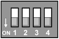
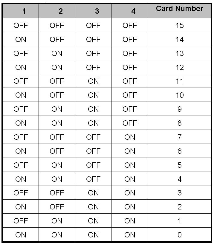
2. Card Identifier
The switch is used to identify card number, default setting is card 15 , and there are two methods to set the card number: • PnP mode Just plug in PCI BUS 4 CHANNELS RELAY OUTPUT / 4 CHANNES PHOTO ISOLATOR INPUT ADAPTER into PCI slot, the PCI BIOS will allocate I/O address to each adapter automatically and assign card number start from 0 to each adapter. You may set any card number at PnP mode, and you need use software tools to distinguish port id. Almost all of the operating systems run at PnP mode. • manual mode Set card number by card identifier switch, the PCI BIOS will assign pre-allocated I/O address to each adapter. Please set different card number to each adapter (do not duplicate card number setting).
|
||||||||||||||||||||||||||||||||||||||||||||||||||||||