|
CHAPTER
5 The Plug and Play features let hardware configuration for IRQ and I/O address is detected by BIOS automatically, so that it need not switch and jumper setting. The on board switch can be used to identify card number by the users (if you do not set the switch, the PnP BIOS will assign card number automatically). Set RS232 or RS422 or RS485 mode for port 1, 2, 3, and 4. Set RS422 terminator for port 1, 2, 3, and 4.
Select
high speed mode or normal speed mode.
Select external clock or internal clock.
Identifies card
number. |
|||||||||||||||||||||||||||
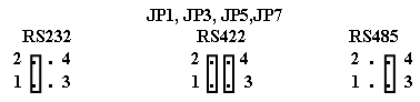
| Under the RS485 mode, all the
RS485 Ports are set to receive mode automatically, while one port use
to send data to the other port, it needs to set RTS signal to 1, to
enter driver mode, then send message or data. After sending message, it
needs to set signal to 0 to enter receive mode again. For RS422 communication, you must set both ports to RS422 terminator mode. The RS485 communication is based on cable sharing method, so that only two ports are set to enable RS422 terminator to avoid signal lose. |
|||||||||||||||||||||||||||
 |
|||||||||||||||||||||||||||
|
JP10
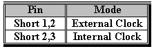
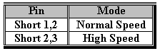
2. Select High Speed or Normal Speed Mode
JP9 The JP9 is used to select high-speed mode or normal speed
mode; to select normal speed, please short pin 1 and 2, to select high
speed, please short pin 2 and 3.
 a.
ST16C554 Chip for Normal Speed

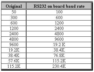
The clock rate is 1.8432MHZ. The baud rate speed up to 115200. Under this configuration, the user setting baud rate is the same as RS232 baud rate. We list in the following. 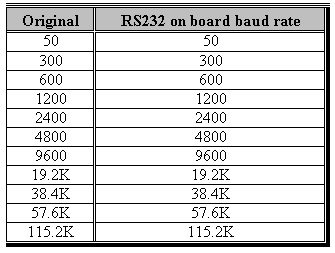 b. ST16C554 Chip for Quadruple Speed JP10 JP9
 The clock rate is 7.3728MHZ. The baud rate speed up to 460K. Under this configuration, the user setting baud rate maps to on board RS232 baud rate are list in the following. Please note that, you device driver may report original baud rate, however the speed of communication line is quadruple speed. 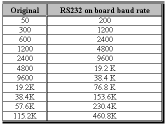 c. XR16C854 Chip for Dual Speed JP10 JP9
The clock rate is 3.6864MHZ. The baud rate speed up to
230K. Under this configuration, the user setting baud rate maps to on
board RS232 baud rate are list in the following. Please note that, you
device driver may report original baud rate, however the speed of
communication line is dual speed.
 d. XR16C854 Chip for Octal Speed JP10 JP9 The clock rate is 14.7456MHZ. The baud rate speed up to 1M. Under this configuration, the user setting baud rate maps to on board RS232 baud rate are list in the following. Please note that, you device driver may report original baud rate, however the speed of communication line is octal speed. 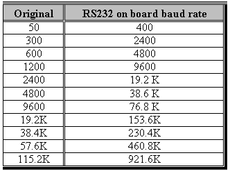
3. Set RS232 or RS422 or RS485 Mode
The JP1 is used to set RS232 or RS422 or RS485 mode for port
1, to short pin 1, pin 2 and open pin 3, pin 4 means set RS232 mode, to
short pin 1, pin 2 and pin 3, pin 4 means set RS422 mode, to open pin
1, pin 2 and short pin 3, pin 4 means set RS485 mode. The JP3, JP5, and
JP7 are used to set communication mode corresponds to port 2, port 3,
and port 4.
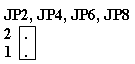
4. Enable/Disable RS422 Terminator
The JP2 is used to set RS422 terminator for port 1, to short
pin 1 and pin 2 means enable RS422 terminator, otherwise, it means
disable RS422 terminator. The JP4, JP6, and J8 are used to set RS422
terminator corresponds to port 2, port 3, and port 4.
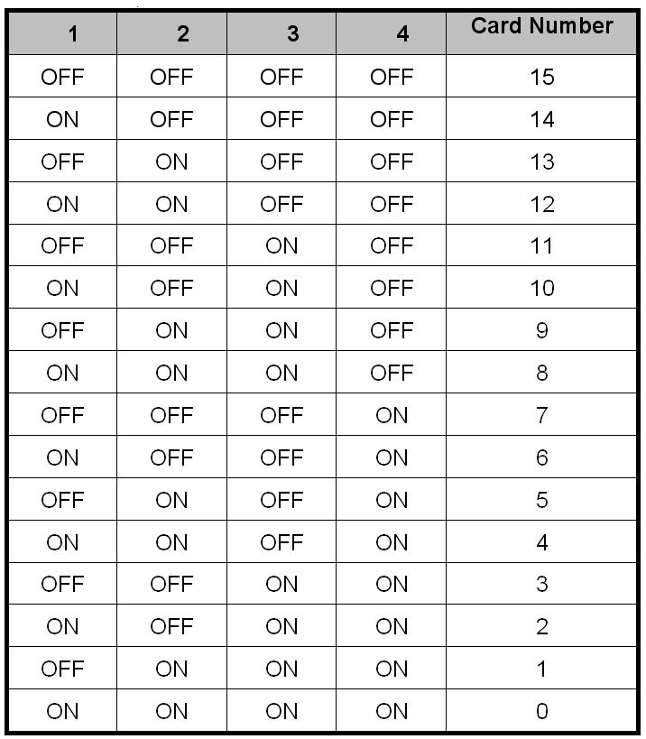
5. Card Identifier
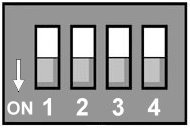
The switch is used to identify card number, default setting is card 15 , and there are two methods to set the card number: • PnP mode Just plug in PCI BUS 4 CHANNELS RELAY OUTPUT / 4 CHANNES PHOTO ISOLATOR INPUT ADAPTER into PCI slot, the PCI BIOS will allocate I/O address to each adapter automatically and assign card number start from 0 to each adapter. You may set any card number at PnP mode, and you need use software tools to distinguish port id. Almost all of the operating systems run at PnP mode. • manual mode Set card number by card identifier switch, the PCI BIOS will assign pre-allocated I/O address to each adapter. Please set different card number to each adapter (do not duplicate card number setting).
 |