CHAPTER 5
SWITCH SETTING
5.1 Introduction
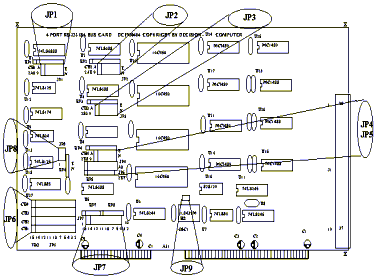
The nine jumper blocks on the
PCCOM ISA bus 4 port adapter must be configured correctly in accordance
with the operating system you are using.
JP1 (Jumper 1)
Determines the I/O address of port 1.
JP2 (Jumper 2)
Determines the I/O address of port 2.
JP3 (Jumper 3)
Determines the I/O address of port 3.
JP4 (Jumper 4)
Determines the I/O address of port 4.
JP5 (Jumper 5)
Selects the interrupt vector address and determines which port is active when an interrupt occurs.
JP6 (Jumper 6)
Selects which interrupt will be used in the range IRQ2 through IRQ15.
JP7 (Jumper 7)
Enable selected interrupt. The selection of this jumper should correspond to the selection of JP6.
JP8 (Jumper 8)
Select delay wait state.
JP9 (Jumper 9)
Select the activation status (low or high) of interrupt vector.
5.2 Configuration for Dip Switch and Jumper
It is important to refer to the
user manual supplied with your operating system to determine the
correct configuration. Although we provide installation advice for
various operating systems, it is not possible to cover all systems in
this user guide. Please contact your supplier if you have any
difficulties with configuration.
IMPORTANT:
CARE MUST BE TAKEN IN SELECTING THE CONFIGURATION OF JUMPERS AND SWITCH
TO ENSURE YOU DO NOT DUPLICATE SETTINGS OF OTHER EQUIPMENT ALREADY
INSTALLED IN YOUR COMPUTER. DUPLICATION OF SETTINGS WILL RESULT IN A
MALFUNCTION OF ONE OR BOTH DEVICES.
Please refer to the following
settings for each switch and jumper block. If you are installing more
than one board, do not duplicate jumper settings for any parameter.
DECISION
COMPUTER INTERNATIONAL CO ., LTD.
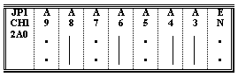
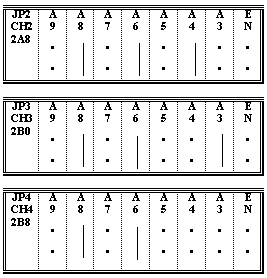
1. I/O Port Address
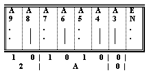
JP1 to JP4 are used to select
UART I/O address for each port. Where JP1 is used to select port 1
address, JP2 is used to select port 2 address etc. Each JP contains A9
to A3 jumper pins and EN jumper pin. The A9 to A3 are used to set
I/O port address, when the corresponding pin is short means 0,
otherwise no pin short means 1. The figure above set the I/O
address to 2A0H. The EN pin is used to enable the selected port, not
short the jumper means enable the port, otherwise, if you short the
jumper means disable this port.
The default setting of this board are:
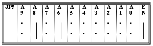
JP5 is used to set the
interrupt vector address. A9 to A0 corresponding to address selection
bit, not short the pin when the user select the bit to 1, otherwise
short the pin to select 0. The default setting of this board is 2BFH.
The EN pin is used to enable the interrupt vector, when short the pin
means enable, otherwise not short the pin means disable interrupt
vector.
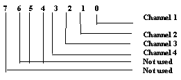
The interrupt vector is used to
detect which of the four channels is creating the interrupt. After the
interrupt vector is enabled, the user may read bit 0 from interrupt
vector address to detect whether channel 1 is creating an interrupt or
not? To read bit 1 to detect whether channel 2 is creating an interrupt
or not? ... etc. If you set active low (JP9 open), when read a
data bit from the interrupt vector is 0, the corresponding channel is
creating an interrupt. When the bit content is 1, there is no interrupt.
3. Interrupt Selection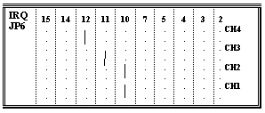
JP6 is a channel interrupt
select matrix, you may select interrupt for each channel. It can
arrange these interrupts in any combination, this means it can set all
ports in different interrupt, or combine several ports into a group to
share the same interrupt. The figures shown above are for CH1 and CH2
to be combined on interrupt 10, CH3 on interrupt 11 and CH4 on
interrupt 12.
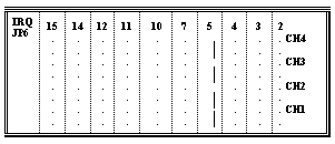
The
default setting of this board is combined to share the same interrupt
(IRQ5).
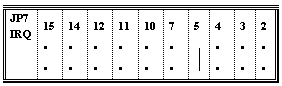
The JP7 is used to enable IRQ2
to IRQ15 bus lines. Note that the selection of these jumpers
should correspond to the selection of the interrupts on the interrupt
select matrix (JP6). For example, if you select IRQ5 and IRQ10 on the
JP6, you need short IRQ5 and IRQ10 of JP7. However, If more than one
boards use common IRQ, only select one board to short the JP7.
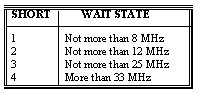
5. Select Wait State

The JP8 is used to select delay wait state.
6.Select Activation Status

The JP9 is used to select the activation status of interrupt. Please see interrupt vector setting section for more details.

If you set active low (JP9
open), when read a data bit from the interrupt vector is 0, the
corresponding channel is creating an interrupt. When the content of bit
is 1, there is no interrupt.
If you set active high (JP9
short), when read a data bit from the interrupt vector is 1, the
corresponding channel is creating an interrupt. When the content of bit
is 0, there is no interrup.
