RS232
CURRENT LOOP CONVERTER
 |
|
RS232
CURRENT LOOP CONVERTER
|
|
|
|
|
The RS232 current loop converter provides an expandable current loop communication for standard RS232 interface. |
||||||||||||||||||||||||||||||||||||||||
| The
features of RS232 current loop converter are : |
||||||||||||||||||||||||||||||||||||||||
|
||||||||||||||||||||||||||||||||||||||||
| |
||||||||||||||||||||||||||||||||||||||||
| The
package contains: |
||||||||||||||||||||||||||||||||||||||||
|
||||||||||||||||||||||||||||||||||||||||
| Hardware
configuration: |
||||||||||||||||||||||||||||||||||||||||
| 1. Block Diagram |
||||||||||||||||||||||||||||||||||||||||
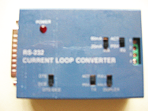
| Observe the figure shown in the following, the RS232 current loop converter contains five switches, one terminal block, and one RS232 DB-25 male connector. | ||||||||||||||||||||||||||||||||||||||||
 |
||||||||||||||||||||||||||||||||||||||||
2. Switch Setting |
||||||||||||||||||||||||||||||||||||||||
|
||||||||||||||||||||||||||||||||||||||||
The SW2 is used to
select Tx active current.
|
||||||||||||||||||||||||||||||||||||||||
The SW3 is used to
select full duplex, half duplex for transmit or receive mode.
|
||||||||||||||||||||||||||||||||||||||||
The SW4 is used to
select Tx passive or active.
|
||||||||||||||||||||||||||||||||||||||||
The SW5 is used to
select Rx passive or active.
|
||||||||||||||||||||||||||||||||||||||||
|
3. Termianal Block
|
||||||||||||||||||||||||||||||||||||||||
|
||||||||||||||||||||||||||||||||||||||||
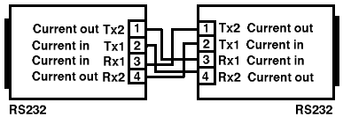
| The terminal block is
used to connect two RS232 current loop converters. The signal
assignment is shown in the follow. |
||||||||||||||||||||||||||||||||||||||||
|
||||||||||||||||||||||||||||||||||||||||
| For full duplex application, please connect it as figure below. | ||||||||||||||||||||||||||||||||||||||||
|
||||||||||||||||||||||||||||||||||||||||
| 4.
Signal Asssignments for DB25 |
||||||||||||||||||||||||||||||||||||||||
|
|
||||||||||||||||||||||||||||||||||||||||
|
A. DTE mode (standard)
|
||||||||||||||||||||||||||||||||||||||||
|
||||||||||||||||||||||||||||||||||||||||
|
B. DCE mode
|
||||||||||||||||||||||||||||||||||||||||
|
||||||||||||||||||||||||||||||||||||||||
|
* The pin 4 (CTS) and
pin 5 (RTS) are shorted together, and the pin 6 (DTR) and pin
20 (DSR) are shorted together in this converter.
|
||||||||||||||||||||||||||||||||||||||||
|
* Some applications
need short pin 6 (DTR) and pin 8 (DCD).
|
||||||||||||||||||||||||||||||||||||||||
| DEVICE
CONNECTION: |
||||||||||||||||||||||||||||||||||||||||
| 1. Installation: | ||||||||||||||||||||||||||||||||||||||||
| To
use RS232 current loop converter, you must connect it by 4 wire
line (24 AWG two twisted pairs), then connect both DB-25 male
connector to PC or devices (we call DEVICE in the follow).
Please noto that, you must set DCE or DTE mode correctly, otherwise it
can not work. Suppose the DEVICE is DTE mode, you must
set the RS232 current loop converter to DCE, otherwise if the
DEVICE is DCE mode, you must set the RS232 current loop converter to
DTE. |
||||||||||||||||||||||||||||||||||||||||
| The full duplex
connection of two RS232 current loop converters are shown in
the follow. |
||||||||||||||||||||||||||||||||||||||||
 |
||||||||||||||||||||||||||||||||||||||||
| If needed, plug in
power adapter to RS232 current loop converter. |
||||||||||||||||||||||||||||||||||||||||
| 2. Loop Back Test |
||||||||||||||||||||||||||||||||||||||||
| To test the RS232 current loop converter, please follow the steps: | ||||||||||||||||||||||||||||||||||||||||
|
1. Set SW1
to DCE. (suppose RS232 port of your computer is DTE)
2. Connect Tx2(#1) to Rx1(#3). 3. Connect 50 to 100 OHM resistor from Tx1(#2) to Rx2(#4). 4. Set the SW4 to Tx active and SW5 to Rx passive. 5. Set the SW3 to full duplex. 6. Run CURTEST.EXE program (which is in the distribution diskette). 7. Key in data, you may see the key in data are shown in the monitor. |
||||||||||||||||||||||||||||||||||||||||
| |
||||||||||||||||||||||||||||||||||||||||
|
NOTE
* Do not forget to connect resistor in
this test stage, otherwise it will damage the devices. |
||||||||||||||||||||||||||||||||||||||||
| * You may set SW4 to
Tx passive and SW5 to Rx active, to tesst another function. |
||||||||||||||||||||||||||||||||||||||||
| 3. Hardware Connection |
||||||||||||||||||||||||||||||||||||||||
| Inthe following,
we will introduce how to connect DB-25 from computerto
computer/device, and also show the signal flow of both RS232 current
loop converters. |
||||||||||||||||||||||||||||||||||||||||
|
A. DCE Mode
|
||||||||||||||||||||||||||||||||||||||||
|
|
||||||||||||||||||||||||||||||||||||||||
|
B. DTE Mode
|
||||||||||||||||||||||||||||||||||||||||
|
|
||||||||||||||||||||||||||||||||||||||||
|
3. Full Duplex
|
||||||||||||||||||||||||||||||||||||||||
|
|
||||||||||||||||||||||||||||||||||||||||
|
||||||||||||||||||||||||||||||||||||||||
| * To
select DTE or DCE, please see the section of DTE mode and DCE
mode. |
||||||||||||||||||||||||||||||||||||||||
|
C. Simplex
Application
|
||||||||||||||||||||||||||||||||||||||||
|
The side 1 is set to
receiver and the side 2 is set to sender.
|
||||||||||||||||||||||||||||||||||||||||
 |
||||||||||||||||||||||||||||||||||||||||
|
||||||||||||||||||||||||||||||||||||||||
|
D. Half
Duplex Application
|
||||||||||||||||||||||||||||||||||||||||
|
|
||||||||||||||||||||||||||||||||||||||||
|
||||||||||||||||||||||||||||||||||||||||
| Case 1: Side 1 is sender, and
side 2 is receiver.
|
||||||||||||||||||||||||||||||||||||||||
| Case 2: Side 2 is sender, and
side 1 is receiver.
|
||||||||||||||||||||||||||||||||||||||||
| |
| |
|||||
Manual |
Test Tool & Sample Code |
Diagram |
UARTs &Line Driver |
||